Rebuilding a rocking piston compressor. - 10/26/14 02:16 AM
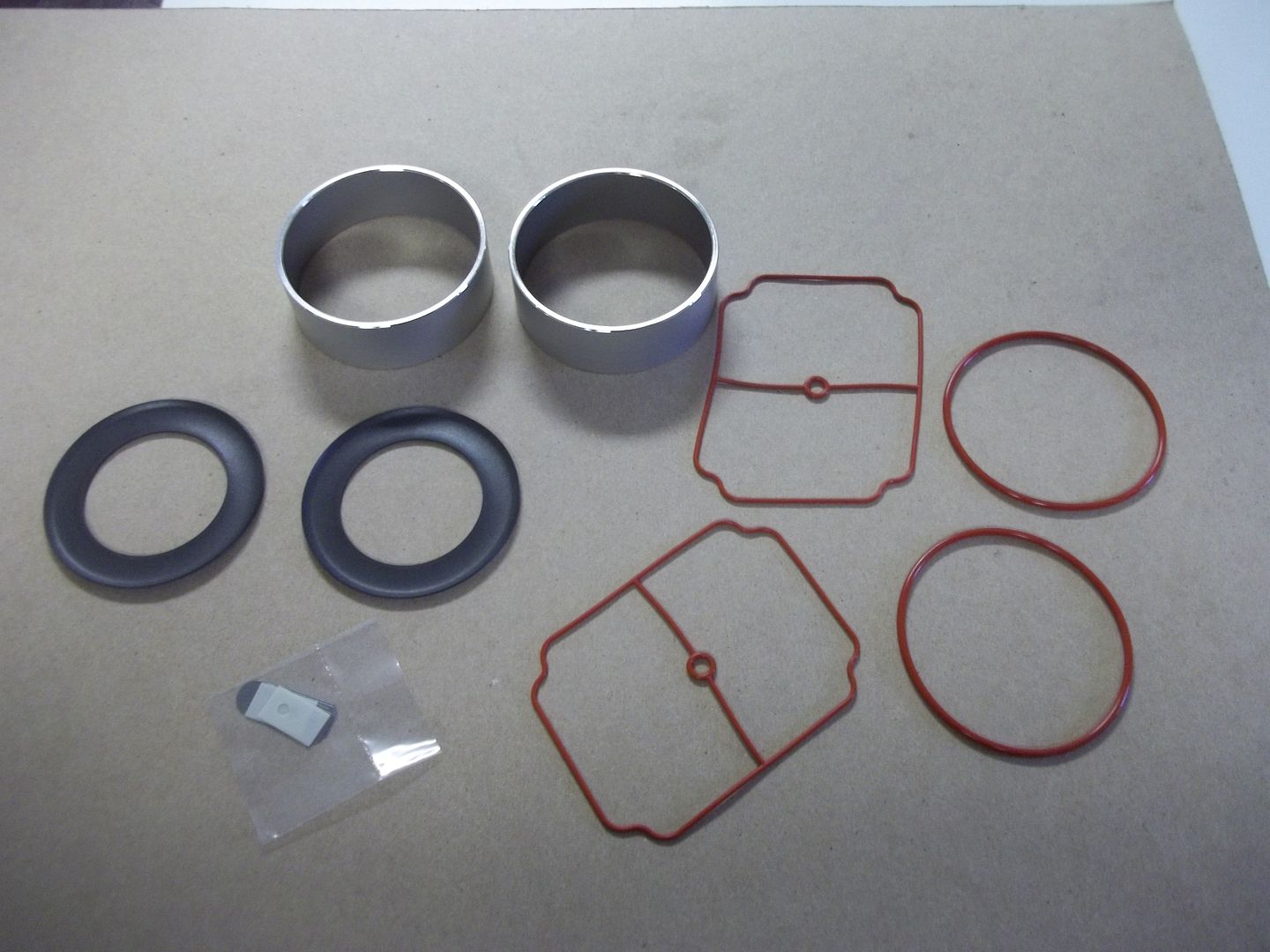
This 2650 series Thomas compressor has run near constant for almost 4 years now, and the diminishing air output is beginning to reflect all those hours of use. So before ice cover sets in, I thought I would do a complete rebuild of the top end. This is what came in the kit: new cylinders, cups, reed valves, and o-ring gaskets.
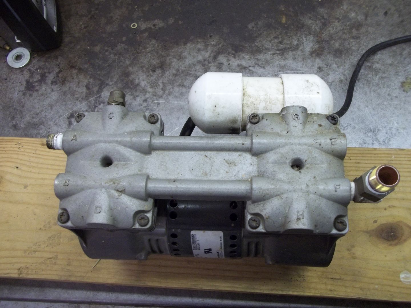
First step was the removal of 8 screws that hold the head on. A T25 Torx driver was needed for this.
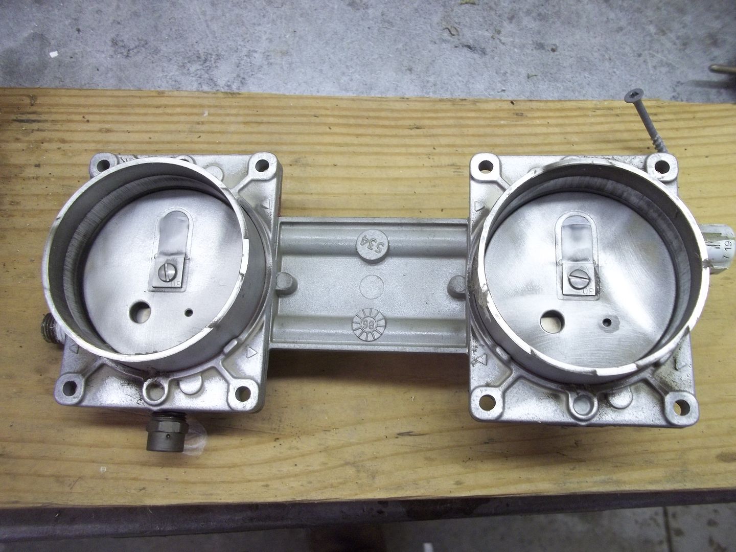
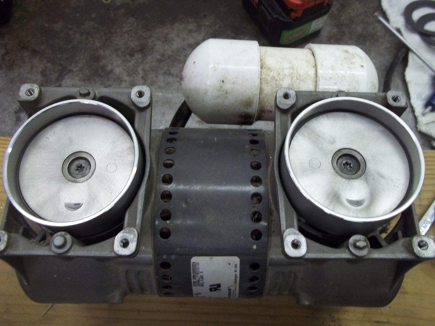
I was surprised to find that the cylinders(?) were essentially free floating, captured between the head and the main body. They came off with the head.
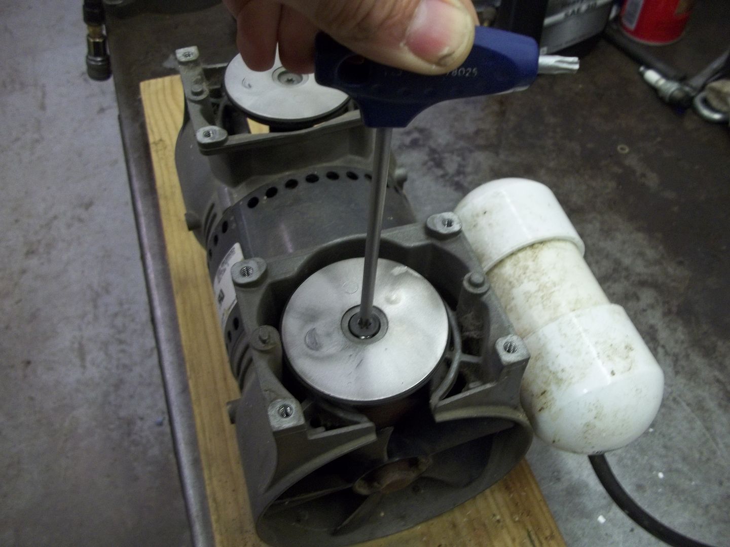
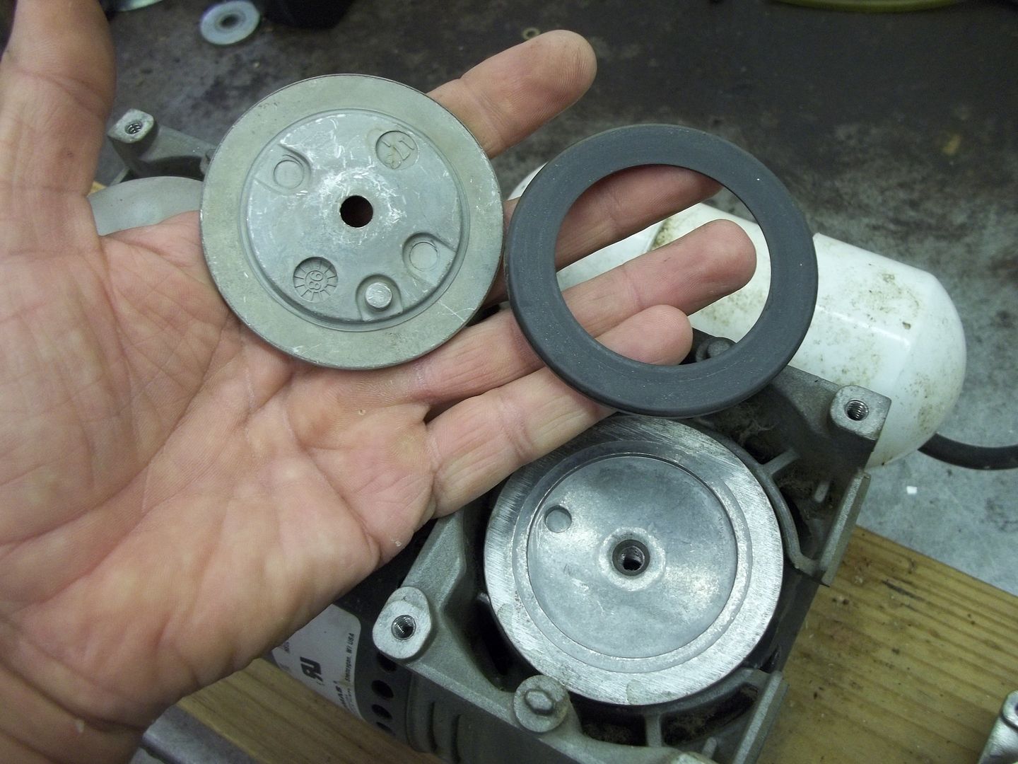
To get to the piston cups, which would be comparable to a piston ring, I had to disassemble the piston by removing one screw.
The piston is made in two pieces, with the cup in between.
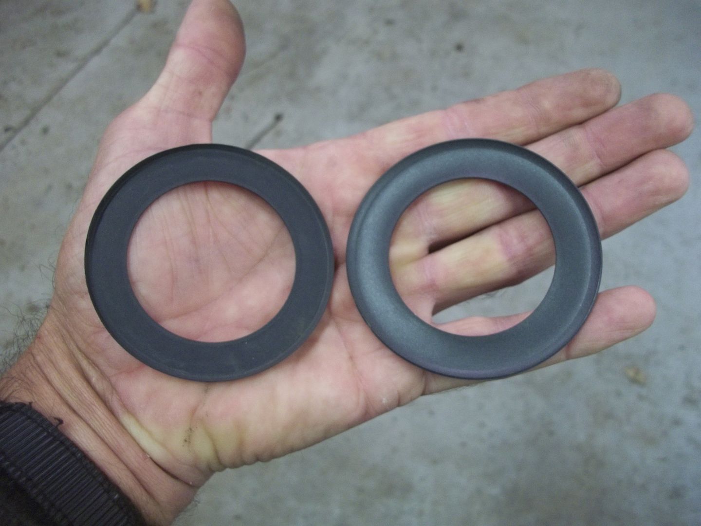
The difference between the old cup on the left, and the new replacement one on the right, is pretty noticeable, as the new one has a larger outside diameter. The old cup tended to stay compressed, while the new one was soft and flexible.
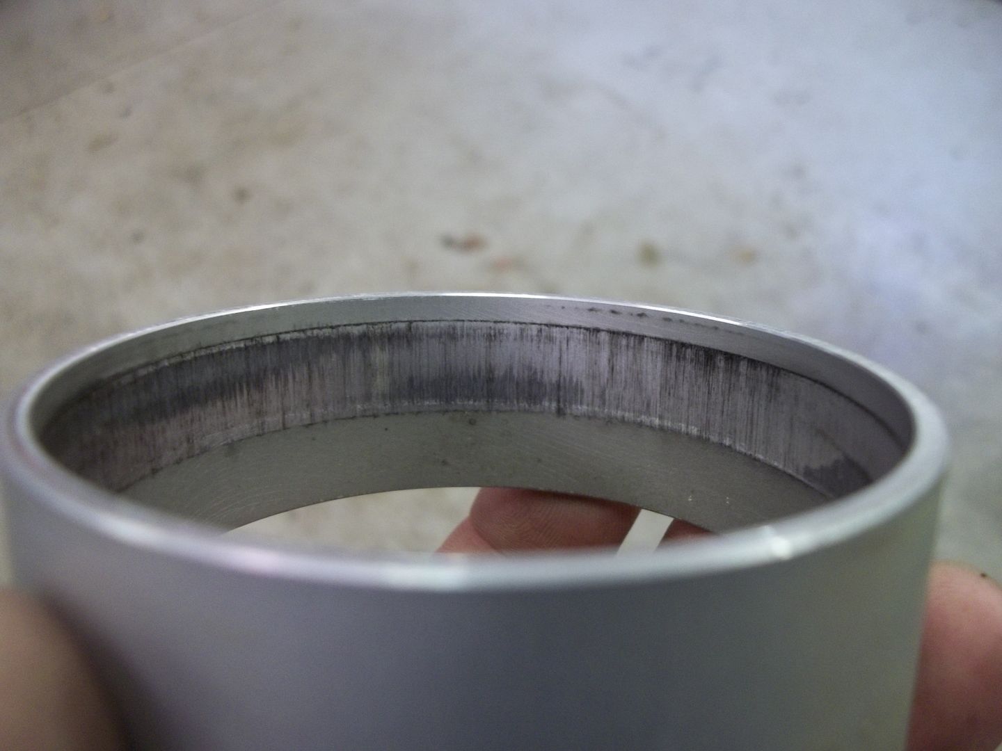
Lots of wear on the cylinders also. A definite ridge could be felt with my finger.
Replacing the cups was the trickiest part of the entire procedure. I finally settled on placing the cup in the cylinder, placing that assembly over the lower piston half, then placing the upper piston half on top of it, and tightening the screw while hoping everything remained centered. Surprisingly, it worked.
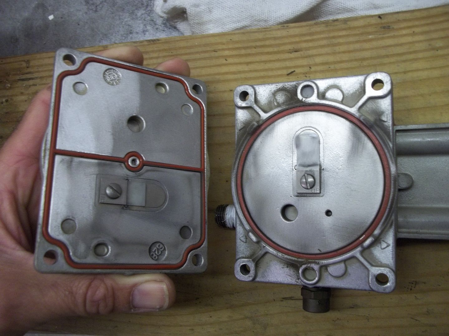
On to the valves. There are 4 total, two for the intake, and two for exhaust...which in this case is the pressure outlet. They are simple, flapper style valves, similar to the old reed valves.
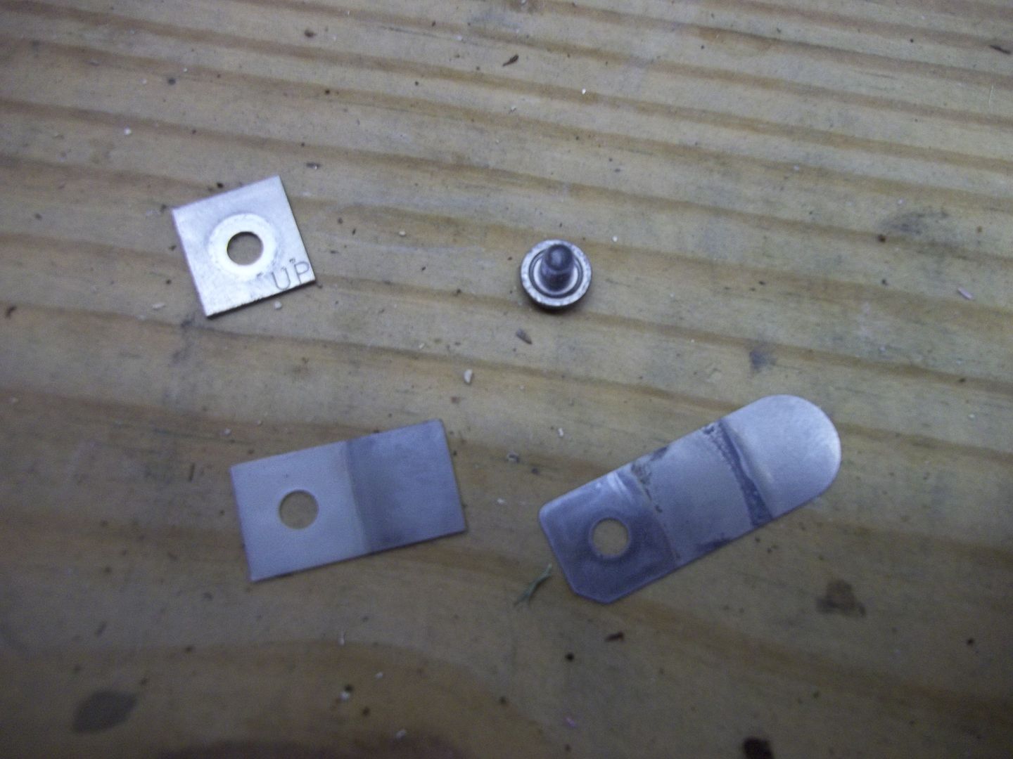
These are the four parts that comprise the valve assemblies. A metal flapper, a rigid stiffener (plastic?), a square metal retainer, and the hold down screw. Note that the two intake valves do not utilize the plastic stiffeners.
From here, it's just a case of replacing the formed O-rings and reassembling. Very straightforward. Once I had everything back together, I hooked up the pressure gauge and flipped the switch. What a difference! I can actually hear the stronger compressor output.
Next step, designing a better air filter.

First step was the removal of 8 screws that hold the head on. A T25 Torx driver was needed for this.

I was surprised to find that the cylinders(?) were essentially free floating, captured between the head and the main body. They came off with the head.

To get to the piston cups, which would be comparable to a piston ring, I had to disassemble the piston by removing one screw.

The piston is made in two pieces, with the cup in between.

The difference between the old cup on the left, and the new replacement one on the right, is pretty noticeable, as the new one has a larger outside diameter. The old cup tended to stay compressed, while the new one was soft and flexible.

Lots of wear on the cylinders also. A definite ridge could be felt with my finger.

Replacing the cups was the trickiest part of the entire procedure. I finally settled on placing the cup in the cylinder, placing that assembly over the lower piston half, then placing the upper piston half on top of it, and tightening the screw while hoping everything remained centered. Surprisingly, it worked.

On to the valves. There are 4 total, two for the intake, and two for exhaust...which in this case is the pressure outlet. They are simple, flapper style valves, similar to the old reed valves.

These are the four parts that comprise the valve assemblies. A metal flapper, a rigid stiffener (plastic?), a square metal retainer, and the hold down screw. Note that the two intake valves do not utilize the plastic stiffeners.

From here, it's just a case of replacing the formed O-rings and reassembling. Very straightforward. Once I had everything back together, I hooked up the pressure gauge and flipped the switch. What a difference! I can actually hear the stronger compressor output.
Next step, designing a better air filter.


