|
Forums36
Topics40,961
Posts557,951
Members18,500
| |
Most Online3,612
Jan 10th, 2023
|
|
|
8 members (Bill Cody, Rick O, Willowwood, Augie, Shorthose, KenHorton, Theo Gallus, rjackson),
1,047
guests, and
172
robots. |
|
Key:
Admin,
Global Mod,
Mod
|
|
|
|
Joined: Oct 2005
Posts: 6,934 Likes: 2
Ambassador
Field Correspondent Lunker
|
OP

Ambassador
Field Correspondent Lunker
Joined: Oct 2005
Posts: 6,934 Likes: 2 |
All right, I just bumped into a little problem with a new GFCI protected circuit.
-
I have a 220v gennie running power into a small garage at the LNP project. The power enters on 2 hots, 1 neutral, and 1 ground. The breaker box also has a ground wire from the neutral buss bar to a copper ground rod.
I ran another 220v circuit out of this same box and out to the boat dock, to another outdoor breaker box with a standard 20 amp double pole breaker. The power is also carried by 2 hots, 1 neutral, and 1 ground.
Then....I ran a 110v circuit from this outdoor breaker box to an exterior outlet in a weatherproof box. I put a GFCI outlet in the weatherproof box.
I want the entire outdoor power feed protected by GFCI, so I purchased a 30 amp double pole GFCI breaker. I selected 30 amp because the feed wire will easily handle it and someday I might need it. I have not changed out the 20 amp double pole standard breaker in the exterior breaker box.
-
When I hooked up the GFCI double pole breaker in the main breaker box in the shed, it would pop whenever I flipped it on. I verified the 2 outdoor circuit hots were attached to the GFCI breaker loads, the outdoor circuit white neutral was attached to the neutral on the breaker, and the breaker pigtail was attached to the neutral buss bar in the breaker box. It still pops the breaker.
I went out and turned off the 20 amp double pole in the exterior breaker box. The GFCI still pops.
I went out and removed the GFCI outlet, knowing that having 2 GFCI controls on one circuit can be problematic. The bare receptacle wires were clear of everything and totally disconnected. The GFCI still pops.
I went back to the main panel and removed the GFCI breaker and replaced it with a standard 30 amp double pole breaker. I replaced the GFCI outlet at the other end and the power worked fine (I regret that I did not have a plug tester to verify the circuit for proper grounding).
-
I don't get it. The only thing I can think of is that the GFCI is a 30 amp and the next link in the circuit is a standard 20 amp breaker. Would that cause the GFCI to trip?
....or
(this can't possibly be, but I gotta ask)
Having the mechanical ground to a copper rod in the ground doesn't create the current flow imbalance that the GFCI is detecting....right?
-
I brought the GFCI breaker home. I just went into the garage and removed the cover on the breaker panel in the garage. I hooked up the pigtail to the common buss bar and pushed the GFCI breaker onto an available pair of spaces. I did not hook up anything further, but there was power to the breaker. I flipped the bar and it did not pop.
I just don't get it.
|
|
|
|
|
Joined: Dec 2006
Posts: 2,086
Lunker
|
|
Lunker
Joined: Dec 2006
Posts: 2,086 |
Maybe its the fluctuation in power from the ginset it doesnt like? Maybe
I subscribe Some days you get the dog,and some days he gets you.Every dog has his day,and sometimes he has two! 
|
|
|
|
|
Joined: Oct 2005
Posts: 1,285 Likes: 1
Lunker
|
|
Lunker
Joined: Oct 2005
Posts: 1,285 Likes: 1 |
First off, I usually run all the wiring then hire an electrician to make the final connections simply because I have no confidence in my electrical abilities. One thing that seems suspect is the ground rod. The generator doesn't require one so maybe this is what is causing you trouble with the GFCI.
I've noticed that when I plug my worm wand into a GFCI outlet, it pops as soon as I touch the soil. Doesn't seem to bother a 15 amp breaker though.
 "The greatest enemy of knowledge is not ignorance, it is the illusion of knowledge." Stephen W. Hawking
|
|
|
|
|
Joined: May 2004
Posts: 13,972 Likes: 276
Moderator Lunker
|

Moderator Lunker
Joined: May 2004
Posts: 13,972 Likes: 276 |
Virtually all I know about GF(C)I circuits is that they are designed to detect small differences in the outgoing (black wire) and returning (white wire) currents and trip if they occur. These are current "leaks" too small to trip a normal circuit breaker. As an example, you plug a leaf blower into a 15A circuit breaker using an extension cord. The connection where it plugs in to the extension cord lays on wet ground and leaks 1 amp of current into the ground. This is way less than the 15 A limit on the circuit breaker, but is enough current to hurt or kill you if you become it's path to ground. This is the kind of situation a GCFI is designed to protect against. I've noticed that when I plug my worm wand into a GFCI outlet, it pops as soon as I touch the soil. Doesn't seem to bother a 15 amp breaker though. The way worm sticks work (yours AND mine), running current in to the ground directly, is like the worst case scenario as far as a GFCI is concerned.
"Live like you'll die tomorrow, but manage your grass like you'll live forever." -S. M. Stirling ![[Linked Image from i.pinimg.com]](https://i.pinimg.com/736x/ed/b5/e7/edb5e7f935843b996cf52be593c9ebd2--smoothie-smooth-collie.jpg)
|
|
|
|
|
Joined: Oct 2007
Posts: 365
Lunker
|
|
Lunker
Joined: Oct 2007
Posts: 365 |
Brettski, take a look at the diagram, and tell me if this is how it is wired? 
Last edited by bbjr; 11/17/08 01:25 PM. Reason: resize image
-Chris 1 acre pond Currently managing: FHM, GSH, GSF, BG, PS, RES, LES, YP, SMB, LMB, HSB, RBT, WE, CC, FHC, and Grass Shrimp 
|
|
|
|
|
Joined: Oct 2005
Posts: 6,934 Likes: 2
Ambassador
Field Correspondent Lunker
|
|
OP
Ambassador
Field Correspondent Lunker
Joined: Oct 2005
Posts: 6,934 Likes: 2 |
Hi Chris, Wow...nice work. Since you put so much effort into this one, I will fill in some deleted details. - The generator does have a ground lug, but I have not connected it (yet). The 220v output plug of the gen-set runs thru a short 10 ga pigtail to a small breaker panel that contains one double pole 20 amp breaker (the pigtail has a male plug on both ends that carries load/load/neutral/ground) 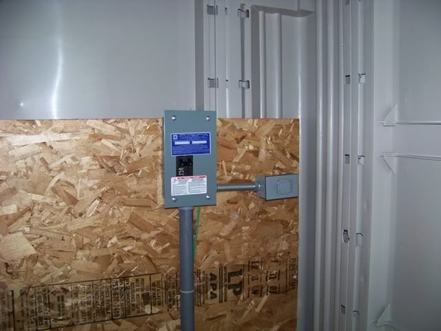 - This breaker box IS grounded to a rod in the ground. From this point, your diagram (after the gen-set) is accurate...except... a) I can't positively verify that the main panel box neutral/ground bar is bonded to the panel. I just assumed it is (my bad?) b) wiring from the main panel to the sub panel is 8 ga c) the sub panel has a removeable double pole 20 amp breaker. The power coming in goes to main power lugs within the box. The neutral and ground are connected to the neutral/ground bar and the bar IS bonded to the panel (it came with a screw and I bonded them together) d) The 120v power to the GFCI outlet is taken directly from one side of the double pole breaker
|
|
|
|
|
Joined: Oct 2005
Posts: 6,934 Likes: 2
Ambassador
Field Correspondent Lunker
|
|
OP
Ambassador
Field Correspondent Lunker
Joined: Oct 2005
Posts: 6,934 Likes: 2 |
Here ya go Chris You can tear this one up; it's a pic of the main panel (just before installing the 30A GFCI double pole breaker). The lower right feed comes in from the gen-set and the lower left goes out to the subpanel on the dock. When I got the GFCI and installed it (onto the wires going out, lower left), I removed the white neutral from the neutral/ground bar and attached it to the neutral lug on the GFCI. I ran the pigtail from the GFCI to the newly vacated lug on the neutral/ground bar. - 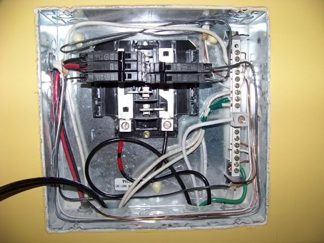 - Does this neutral/ground bar also have a hardwire screw that ties it to the panel to ground it?
|
|
|
|
|
Joined: Oct 2007
Posts: 365
Lunker
|
|
Lunker
Joined: Oct 2007
Posts: 365 |
Brettski,
I may be confused, if I am, forget the following info. From your description above, I am assuming there are a total of 3 panels.
I can't tell from the picture (second pic), but is the main panel's (I will refer to this as panel 2) neutral bar isolated from the metal cabinet? or, is there metal to metal contact between the bar and the panel? Since you have, in essence, a "main" panel (your first pic, and I will now refer to this as panel 1) that feeds this panel (panel 2), and panel 1 in the first pic is grounded to a ground rod and has the neutral bonded to the panel(right or wrong?), any panel after that should not have the neutral bar bonded to the ground. So, your outdoor sub-panel (I am assuming it is not pictured, we will call this panel 3)and panel 2, should have isolated grounds and neutrals.
Is there a reason you are using a 2-pole breaker (understanding that you are only using one phase) for the GFCI outlet, rather than using a single pole breaker?
Other than these couple things, everything should be okay, unless I misunderstood something.
-Chris 1 acre pond Currently managing: FHM, GSH, GSF, BG, PS, RES, LES, YP, SMB, LMB, HSB, RBT, WE, CC, FHC, and Grass Shrimp
|
|
|
|
|
Joined: Oct 2005
Posts: 6,934 Likes: 2
Ambassador
Field Correspondent Lunker
|
|
OP
Ambassador
Field Correspondent Lunker
Joined: Oct 2005
Posts: 6,934 Likes: 2 |
Brettski,
I may be confused, if I am, forget the following info. From your description above, I am assuming there are a total of 3 panels. correct
I can't tell from the picture (second pic), but is the main panel's (I will refer to this as panel 2) neutral bar isolated from the metal cabinet? or, is there metal to metal contact between the bar and the panel? I don't know, but I have another one at home (in stock) that I can review and letcha know tonite
Since you have, in essence, a "main" panel (your first pic, and I will now refer to this as panel 1) that feeds this panel (panel 2), and panel 1 in the first pic is grounded to a ground rod (yes, ground wire is connected directly to the neutral/ground bar inside the panel) and has the neutral bonded to the panel(right or wrong?) not sure if it is; will find out this coming weekend, any panel after that should not have the neutral bar bonded to the ground. So, your outdoor sub-panel (I am assuming it is not pictured, we will call this panel 3)and panel 2, should have isolated grounds and neutrals.
So, in summary, you are saying that panel #1 (at the gen-set) should have a neutral/ground bar bonded to the panel AND this should also be grounded to a rod in the soil. Any and all following panels should NOT have the neutral/ground bar bonded to the panel, nor should they be grounded to a rod in the soil. That being said, there is a continuous, uninterrupted neutral wire and ground wire that ties all the neutral/ground bars together (in all 3 panels). That makes all of them grounded to the 1st panel (at the gen-set) which in turn is grounded to the soil with a rod. So...what's the difference if I isolate the 2nd and 3rd panels? They still each have a path back to the soil.
Is there a reason you are using a 2-pole breaker (understanding that you are only using one phase) for the GFCI outlet, rather than using a single pole breaker? This way, I still have the option of 220v at the dock....who knows if I would ever need it, but I had the wire, I had the conduit installed....why not, right?
Other than these couple things, everything should be okay, unless I misunderstood something. Thanks for lookin' over my shoulder; this is giving me a headache for a good reason
|
|
|
|
|
Joined: Oct 2007
Posts: 365
Lunker
|
|
Lunker
Joined: Oct 2007
Posts: 365 |
Brettski,
I may be confused, if I am, forget the following info. From your description above, I am assuming there are a total of 3 panels. correct
I can't tell from the picture (second pic), but is the main panel's (I will refer to this as panel 2) neutral bar isolated from the metal cabinet? or, is there metal to metal contact between the bar and the panel? I don't know, but I have another one at home (in stock) that I can review and letcha know tonite
Since you have, in essence, a "main" panel (your first pic, and I will now refer to this as panel 1) that feeds this panel (panel 2), and panel 1 in the first pic is grounded to a ground rod (yes, ground wire is connected directly to the neutral/ground bar inside the panel) and has the neutral bonded to the panel(right or wrong?) not sure if it is; will find out this coming weekend, any panel after that should not have the neutral bar bonded to the ground. So, your outdoor sub-panel (I am assuming it is not pictured, we will call this panel 3)and panel 2, should have isolated grounds and neutrals.
So, in summary, you are saying that panel #1 (at the gen-set) should have a neutral/ground bar bonded to the panel AND this should also be grounded to a rod in the soil. Any and all following panels should NOT have the neutral/ground bar bonded to the panel, nor should they be grounded to a rod in the soil. That being said, there is a continuous, uninterrupted neutral wire and ground wire that ties all the neutral/ground bars together (in all 3 panels). That makes all of them grounded to the 1st panel (at the gen-set) which in turn is grounded to the soil with a rod. So...what's the difference if I isolate the 2nd and 3rd panels? They still each have a path back to the soil. NEC code does not allow for this, because what you are doing is creaing parallel paths to ground. From the 2002 NEC Handbook 408.20...
A seperate equipment grounding conductor terminal bar must be installed and bonded to the panelboard for the termination of feeder and branch-circuit equipment grounding conductors. Where installed within service equipment, this terminal is bonded to the neutral terminal bar. Any other connection between the equipment grounding terminal bar and the neutral bar, other than allowed in 250.32, is not permitted. If this downstream connection occurs, current flow in the neutral or grounded conductor would take parallel paths through the equipment grounding conductors (the raceway, the building structure, or earth, for example) back to the service equipment. Normal load currents flowing on the equipment grounding conductors could create a shock hazard. Exposed metal parts of equipment could have a potential difference of several volts created by the load current on the grounding conductors. Another safety hazard created by this effect, where subpanels are used, is arcing or loose connections at connectors and raceway fittings, for example, creating a potential fire hazard.
Is there a reason you are using a 2-pole breaker (understanding that you are only using one phase) for the GFCI outlet, rather than using a single pole breaker? This way, I still have the option of 220v at the dock....who knows if I would ever need it, but I had the wire, I had the conduit installed....why not, right?
Other than these couple things, everything should be okay, unless I misunderstood something. Thanks for lookin' over my shoulder; this is giving me a headache for a good reason
-Chris 1 acre pond Currently managing: FHM, GSH, GSF, BG, PS, RES, LES, YP, SMB, LMB, HSB, RBT, WE, CC, FHC, and Grass Shrimp
|
|
|
|
|
Joined: Oct 2007
Posts: 365
Lunker
|
|
Lunker
Joined: Oct 2007
Posts: 365 |
The first thing I would do when you get back to your place, is to make sure that the neutral bars are not bonded on the sub-panels, and that it is in the main panel. If the GFCI breaker is still tripping, with the power off, remove one of the wires off the GFCI breaker (cap it with a wire nut) and try turning power back on and flipping the breaker on. If it still trips, try putting that wire that you removed back into the breaker (with power off, of course) and remove the opposite wire, cap it, and try turning on power and the breaker again. If the breaker does not trip with one of the wires removed, most likely a skinned/damaged wire is at fault. I am doubting this is the case, because your ground wire would also have to be skinned somewhere in the pipe. If the breaker still trips after this testing, see if it will hold without either wire hooked up.
I talked with my dad about this, he has about 25 years more experience than I do, and he is not confident that the GFCI breaker would perform like you are expecting even if it were working correctly. He recommended using a normal 2-pole breaker in panel 2, and using single pole GFCI breakers in panel 3 if you are wanting to protect those circuits. He is also thinking that the "dirty" power the generator may be producing, could have something to do with the breaker not working correctly.
-Chris 1 acre pond Currently managing: FHM, GSH, GSF, BG, PS, RES, LES, YP, SMB, LMB, HSB, RBT, WE, CC, FHC, and Grass Shrimp
|
|
|
|
|
Joined: Oct 2007
Posts: 365
Lunker
|
|
Lunker
Joined: Oct 2007
Posts: 365 |
One more question, do you have pvc or rigid conduit run from panel 2 to panel 3? If metal, then you may very well have a slightly damaged wire. It may be picking up moisture in the pipe and losing some potential to ground, enough to trip.
-Chris 1 acre pond Currently managing: FHM, GSH, GSF, BG, PS, RES, LES, YP, SMB, LMB, HSB, RBT, WE, CC, FHC, and Grass Shrimp
|
|
|
|
|
Joined: Oct 2005
Posts: 6,934 Likes: 2
Ambassador
Field Correspondent Lunker
|
|
OP
Ambassador
Field Correspondent Lunker
Joined: Oct 2005
Posts: 6,934 Likes: 2 |
The conduit is PVC. Of course, the possibility exists that a wire was skinned, but it did work fine on a standard dbl pole breaker.
-
I think I need you to clarify the phrase "neutral bars are not bonded on the sub-panels". I assume that you mean that there is a hardwired electric link between the neutral/grounding bar and the actual distribution box that encloses it. For instance, panel #3 (the last panel, outside at the dock) came with a self tapping screw that can be screwed thru the neutral/grounding bar and into the back of the actual metal box. I did install it. Assuming my assumptions above are correct, how does this make any difference in the current flow path?
|
|
|
|
|
Joined: Oct 2007
Posts: 365
Lunker
|
|
Lunker
Joined: Oct 2007
Posts: 365 |
The conduit is PVC. Of course, the possibility exists that a wire was skinned, but it did work fine on a standard dbl pole breaker.
-
I think I need you to clarify the phrase "neutral bars are not bonded on the sub-panels". I assume that you mean that there is a hardwired electric link between the neutral/grounding bar and the actual distribution box that encloses it. For instance, panel #3 (the last panel, outside at the dock) came with a self tapping screw that can be screwed thru the neutral/grounding bar and into the back of the actual metal box. I did install it. Assuming my assumptions above are correct, how does this make any difference in the current flow path? That is correct. The bonding screw needs to be removed from panel 3. Panels usually have a strap or a screw to bond the neutral bar to the enclosure. Straps are normally factory installed and must be removed if necessary, and screws are the opposite. To answer the question on current flow, I've copied and pasted a post from a fellow on Mike Holt's Forum (a very good forum for electricians, btw)... Originally Posted by Charlie B
Why grounds and neutrals are tied only at the main service, and not at a subpanel.
Reference: NEC article 250.42.
We need to start by noting two things: (1) Current is always seeking a path back to its source, and (2) Current will take every available path it can find.
The function of the equipment grounding conductors (EGC), that ones that connect to the ground bar in the panel, is to carry fault current. If a fault occurs with a piece of equipment, such that a hot conductor comes into contact with the case or other external metal part, any person who touches that equipment is going to get a shock. The shock can be enough to kill, but the current will not be high enough to cause the breaker to trip.
However, with the EGC creating a path from the case back to the ground bar, then via the ground screw or bonding jumper to the neutral bar, the current in this path will be high enough to trip the breaker. This will terminate the event before the person can receive a fatal shock. That is why the ground and neutral buses are connected at the main service disconnecting means � to complete the current path from the fault point back to the source. In this context, I am treating the main panel as the "source." Once the current gets to that point, it has nowhere else go.
If you also connect the ground and neutral at a subpanel, then there will be two paths for current to flow back to the source during normal operation. Current will be flowing in the neutral most of the time (unless the loads running at the moment are perfectly balanced among the phases). But with the ground and neutral tied together both at the main panel and at the subpanel, the EGC will be in parallel with the neutral wire. Therefore, the EGC will carry current. This will cause the external metal parts of each and every component that has an EGC its to become energized. You could not safely touch anything in the facility. __________________
Charles E. Beck, P.E., Seattle
-Chris 1 acre pond Currently managing: FHM, GSH, GSF, BG, PS, RES, LES, YP, SMB, LMB, HSB, RBT, WE, CC, FHC, and Grass Shrimp
|
|
|
|
|
Joined: Oct 2005
Posts: 6,934 Likes: 2
Ambassador
Field Correspondent Lunker
|
|
OP
Ambassador
Field Correspondent Lunker
Joined: Oct 2005
Posts: 6,934 Likes: 2 |
OK...it's getting fuzzier for me.
Let's go back to my actual grounding practice. This might be what you are trying to tell me....maybe not.
On panel #1, I ran a ground wire directly from the neutral bar (inside the box; the bar with the current neutral attached) to a ground rod in the soil. Correct procedure?
On panel #2, I did exactly the same thing. Correct procedure?
-
What I cannot understand is: how does connecting the neutral bar to the host box create another path for the current to follow? Once the box becomes part of the circuit, where does it lead the current to that causes a new path? (remember that I am using PVC as the conduit, so it will not conduct anything further from the box)
|
|
|
|
|
Joined: Oct 2005
Posts: 6,934 Likes: 2
Ambassador
Field Correspondent Lunker
|
|
OP
Ambassador
Field Correspondent Lunker
Joined: Oct 2005
Posts: 6,934 Likes: 2 |
Let me try this...tell me if I'm gettin' closer or further away.
In panel #1, the neutral bar should be bonded to the panel. Running a ground wire from this neutral bar to a ground rod is correct procedure. The 4th service wire that runs to panel #2 is the ground wire that is also connected to the neutral bar in panel #1.
In panel #2 (regarding the 4 inbound wires from panel #1) the neutral bar only sees connection with the white neutral current wire. The inbound ground wire will bond to the panel and it is OK to run this further to another ground rod. By no means should I connect the ground and neutral (this includes making sure that there is no bond between the neutral bar and the panel).
In panel #3, same story as panel #2.
#
|
|
|
|
|
Joined: Oct 2007
Posts: 365
Lunker
|
|
Lunker
Joined: Oct 2007
Posts: 365 |
What I cannot understand is: how does connecting the neutral bar to the host box create another path for the current to follow? Once the box becomes part of the circuit, where does it lead the current to that causes a new path? (remember that I am using PVC as the conduit, so it will not conduct anything further from the box) I'm going to get back to you on this. I want to make sure I get the explanation correct, so it will take me a few days to review.
-Chris 1 acre pond Currently managing: FHM, GSH, GSF, BG, PS, RES, LES, YP, SMB, LMB, HSB, RBT, WE, CC, FHC, and Grass Shrimp
|
|
|
|
|
Joined: Oct 2007
Posts: 365
Lunker
|
|
Lunker
Joined: Oct 2007
Posts: 365 |
Let me try this...tell me if I'm gettin' closer or further away.
In panel #1, the neutral bar should be bonded to the panel. Running a ground wire from this neutral bar to a ground rod is correct procedure. The 4th service wire that runs to panel #2 is the ground wire that is also connected to the neutral bar in panel #1.
In panel #2 (regarding the 4 inbound wires from panel #1) the neutral bar only sees connection with the white neutral current wire. The inbound ground wire will bond to the panel and it is OK to run this further to another ground rod. By no means should I connect the ground and neutral (this includes making sure that there is no bond between the neutral bar and the panel).
In panel #3, same story as panel #2.
This is correct, other than you shouldn't need any additional ground rods past the first one (assuming that in your area, local codes say one ground rod is sufficient) on panel 1. I don't think it will hurt anything to have more down the line since you ran a ground wire that interconnects the panels, but I will double check this, also.
-Chris 1 acre pond Currently managing: FHM, GSH, GSF, BG, PS, RES, LES, YP, SMB, LMB, HSB, RBT, WE, CC, FHC, and Grass Shrimp
|
|
|
|
|
Joined: Oct 2005
Posts: 6,934 Likes: 2
Ambassador
Field Correspondent Lunker
|
|
OP
Ambassador
Field Correspondent Lunker
Joined: Oct 2005
Posts: 6,934 Likes: 2 |
...many thanks again, Chris, as I get a valuable on-line tuneup.
-
So, in summary, once the neutral and ground leave the first (main) panel, they should not cross paths again....period.
|
|
|
|
|
Joined: Oct 2005
Posts: 6,934 Likes: 2
Ambassador
Field Correspondent Lunker
|
|
OP
Ambassador
Field Correspondent Lunker
Joined: Oct 2005
Posts: 6,934 Likes: 2 |
bbjr RULES !!!
I just got back from the pond project. First job was to tune up the wiring per bbjr's instruction. I completely separated all the grounds from the neutrals in all downstream boxes. That did the trick! Thanks bbjr.
So...this is just one more reason to always have a separate continuous ground all the way back to the main panel. Whether it's metal conduit or a 4th wire, now it makes even better sense.
Oh, and btw, I did hook up the downstream ground rod at the second box, but only to the grounds collected on the segregated grounding bar that I installed. No prob's; worked fine.
|
|
|
|
|
Joined: Oct 2007
Posts: 365
Lunker
|
|
Lunker
Joined: Oct 2007
Posts: 365 |
Good to hear, Brettski! I haven't forgot about your question, either, I just got home late from work most of last week and did not have a chance to look it up. Next week looks pretty slow, workwise, so I should be able to get back to you.
-Chris 1 acre pond Currently managing: FHM, GSH, GSF, BG, PS, RES, LES, YP, SMB, LMB, HSB, RBT, WE, CC, FHC, and Grass Shrimp
|
|
|
|
|
Joined: Oct 2007
Posts: 365
Lunker
|
|
Lunker
Joined: Oct 2007
Posts: 365 |
What I cannot understand is: how does connecting the neutral bar to the host box create another path for the current to follow? Once the box becomes part of the circuit, where does it lead the current to that causes a new path? (remember that I am using PVC as the conduit, so it will not conduct anything further from the box) I'm going to get back to you on this. I want to make sure I get the explanation correct, so it will take me a few days to review. From my understanding and further reading, the main problem that could occur in this situation, Brettski, is if the neutral conductor were to become open between panel 2 and panel 1, for instance, then current would energize the metal cabinet of panel 2 and any metal object that is grounded to the circuit. So let's say that you are using a drill with a metal case plugged into a circuit off of panel 2, and for some reason the neutral between panel 1 and 2 becomes open (possibly from a loose connection or any other reason) you will most likely be shocked as current is now using the ground wire to flow back to it's original source (panel 1). Hope this helps. Also, about the additional ground rod, you probably did it the correct way. This is open to interpretation of the code as to whether or not the sub-panel was mounted to a "structure".
Last edited by bbjr; 11/28/08 08:25 PM. Reason: inserted the word "wire" for clarification
-Chris 1 acre pond Currently managing: FHM, GSH, GSF, BG, PS, RES, LES, YP, SMB, LMB, HSB, RBT, WE, CC, FHC, and Grass Shrimp
|
|
|
|
|
Joined: Oct 2005
Posts: 6,934 Likes: 2
Ambassador
Field Correspondent Lunker
|
|
OP
Ambassador
Field Correspondent Lunker
Joined: Oct 2005
Posts: 6,934 Likes: 2 |
I learned something from this, Chris.
Regretfully, it assures me that there are others (like myself) that are very handy and certain that they have hooked things up correctly because everything works and the 3-light plug checker shows "all systems go". Maybe they really aren't...?
For instance, I know that I have a sub-panel out in my garage of my principal residence. I also know that the neutrals and the grounds are all connected to the same buss bar inside the subpanel load center within the garage. This should also be changed to isolate the grounds from the neutrals....right?
|
|
|
|
|
Joined: Oct 2007
Posts: 365
Lunker
|
|
Lunker
Joined: Oct 2007
Posts: 365 |
I learned something from this, Chris.
Regretfully, it assures me that there are others (like myself) that are very handy and certain that they have hooked things up correctly because everything works and the 3-light plug checker shows "all systems go". Maybe they really aren't...?
For instance, I know that I have a sub-panel out in my garage of my principal residence. I also know that the neutrals and the grounds are all connected to the same buss bar inside the subpanel load center within the garage. This should also be changed to isolate the grounds from the neutrals....right? It kind of stinks for me, too, b/c sometimes (I just recently had this happen, actually) you go into a remodel and notice that things are not safe or not to code, and it is my responsibility to bring these items up to code (especially if I work on any part of the area) even though I may not have been hired for that specific purpose. And, some people aren't too happy about having to pay for work done when "things were workin' fine before" (their quote)  . What you did, although it could potentially be dangerous, is not too bad, since the likely hood of the neutral becoming open is not great. However, the potential is there, and that is what most of the codes in the NEC are designed for. Is the sub-panel in the garage wired like the ones at your property, with two hots, a neutral, and a ground coming from the main to the sub? If so, then yes, the neutral bar should be isolated from the metal enclosure, and a seperate ground bar should be used for the grounds.
-Chris 1 acre pond Currently managing: FHM, GSH, GSF, BG, PS, RES, LES, YP, SMB, LMB, HSB, RBT, WE, CC, FHC, and Grass Shrimp
|
|
|
|
|
Joined: Feb 2005
Posts: 4,025 Likes: 1
Lunker
|
|
Lunker
Joined: Feb 2005
Posts: 4,025 Likes: 1 |
I have been following the discussion with interest and am slightly confused, not by the interpretation of the wiring, but by the change in code, or concept. First, a question for Brettski:
Did the sub-panel have a separate neutral bus that was electrically isolated from the metal frame? If so, what type of insulator and how was the bus mounted?
Next question is rhetorical: why did it take so long for this to be thought out and the code changed? Or, maybe I am missing something in it all. Possibly enough people got tickled while using older metal electrical tools with the neutral of the cord connected to the metal case, or the cord inside got chafed or broken and made contact with the metal which caused a tingle. What would they have to touch other than the appliance to get the tingle? Not ground, as there would be no difference in potential.
Is it possible that the code was changed so that GFCI outlets, which are much more commonly used recently, would work correctly in more instances?
|
|
|
Moderated by Bill Cody, Bruce Condello, catmandoo, Chris Steelman, Dave Davidson1, esshup, ewest, FireIsHot, Omaha, Sunil, teehjaeh57 |
|


